

Calculate the required bearing area for the shear lug: Areq = Vapp / (0.85. φ. fc™) φ = 0.65 b. Determine the shear lug dimensions, assuming that bearing occurs only on the portion of the lug below the grout level. Assume a value of W, the lug width, on the basis of the known base plate size to find H, the total height.

Top lifting lug, 26.53 MPa (3,850 lb/in2) for the I-Beam and gusset plates, and 37,90 MPa (5,500 lb/in2) for the lower lifting lugs. The hand calculations in Appendix A determined that the maximum stress in the lower section of the lifting beam is 68.23 MPa (9,903 lb/in2) and occurs in the. There are a few hits if you search this particular forum for 'lifting lug calculation' which may be of help to you. There is an ASME standard called 'ASME BTH-1 Design of Below-the-Hook Lifting Devices' which provides minimum structural design requirements for below-the-hook lifting devices, such as your lifting lugs. Lifting Lug Crosby Shackles Dynamic Impact Factor Skew Load Factor Typ factors used in lifts A An ANGLE Ap b d DIA DIA1 e f FWS fx fxa fxb Fy fya fyb h Ip Ix Iy Lw P Pb PER Ph 'Crosby Shackles'!PrintArea 'Dynamic Impact Factor'!PrintArea 'Lifting Lug'!PrintArea 'Skew Load Factor'!PrintArea 'Typ factors used in lifts'!PrintArea Pt Pvert SF.
Lifting Lugs Manual Calculation Pdf
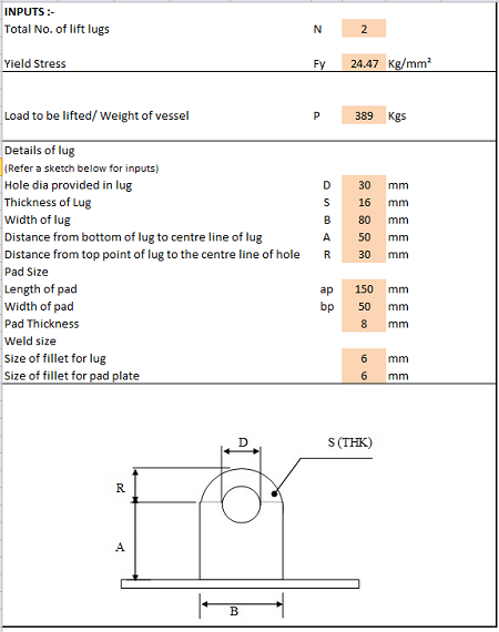
Lug Dimensions: Height of hole centreline, H = Width of Lug, W L = Radius of Lug, R = Diameter of Hole, DH = Thickness of Lug, tL = Allowable Stresses: Lug Material Allowable Tension Stress, 0.6 x Fy = Allowable Shear Stress, 0.4 x Fy =
20000 kgs = 1 2.0 60 degrees 40,000 kgs =
44,092 lbs
88,184 lbs
120 mm = 300 150 60 28
4.72 inch
mm = mm = mm = mm =
11.81 5.91 2.36 1.10
A 36 Fy = 1,519 Kg/cm2 = 1,012 Kg/cm2 =
inch inch inch inch
36,000 psi 21,600 psi 14,400 psi
DH/2R = 0.20 Stress-Concentration Factor (near hole), K = 2.5 (for flat plate with centrally located circular hole in tension based on DH/2R value)
Tension Stresses in the Lug: Weight in each Lug, W = Cable Tension at Lug, F = Inertia Moment of Lug, IL = Stress at Lug to Beam Joint = ST = F.cos (q). H.(W L/2)/IL +
40,000 kgs = 46,188 kgs = 6,300 cm4 = 1,136 Kg/cm2 =
F.sin(q)/(W L.tL) Stress at near the hole = ST = K .F. sin (q) / [(2.R -DH).tL]
88,160 lbs 101,798 lbs 151.36 in4 16,153 psi Safe
Ratio =
Safe
21,160 psi Ratio = 97.96%
Safe
3,909 psi Ratio = 27.15%
Safe
4,887 psi Ratio = 33.93%
1,488 Kg/cm2 =
74.78%
Shear Stresses in the Lug: Stress at Lug to Beam Joint = SS = F.cos(q) / (tL.W L)
275 Kg/cm2 =
Stress at near the hole = SS = F.cos(q) / [(2.R - DH).tL]
344 Kg/cm2 =
Page 5
Stresses in Weld: The calculation used is conservative as it only includes top fillet welds (actual stresses are lower) Leg size of fillet weld, LW = use 45 degree fillet weld Throat size of fillet feld, tW =
17.68 mm =
0.70 in
Length of weld, Ww1 = 2.W L + 2.tL
656.0 mm =
25.83 in
1,743.4 mm =
68.64 in
530,330 mm3 =
32.36 in3
Length of weld including welding in web of beam, W
25.0 mm =
0.98 in
W w2 = W w1 + W L + 2.Hbeam Section Modulus of weld lines, SW = SW= tw.W L2/3 Efficiency of weld, n = Allowable Load on weld Tension Stress at the weld = ST=[F.cos(q).H/SW+ F.sin(q)/ (W w2.tw)] / n Shear Stress at the Weld = ST=[ F.cos(q)/ (W w1.tw)]/ n
100% 675 Kg/cm2 =
9,600 psi
652 Kg/cm2 =
9,276 psi Safe
Ratio =
Safe
2,832 psi Ratio = 29.50%
30.86 Kg/cm2 =
96.62%